Feeds:
Posts
Comments

Mario writes,

I wanted to ask you if among all those great blog-tutorials of yours, there is simple ball-to-ball collision resonse tutorial. Like billiard kind of 2D physics? I need it for a game Im working on that needs collision response between circular asteroids. (including mass)
If not, would you please consider writing one?

There probably is, but it’ll be buried somewhere on the blitzbasic.com forums. So, here’s a new one!

The key insight for ball-to-ball collisions is that, at the moment of impact, the distance between the two balls is the sum of their radii, and the repulsive force is applied along the line between their centres. I’m going to use a lot of vector maths here, because it makes the maths a lot clearer.

So, the first task to detect a collision is to get the distance between the centres of the two balls. If the distance is less than their radii added together, then the balls have collided.

I’ll build up what needs to happen next through a few example cases. I’m not going to really explain the mechanics in depth because there’s loads of messy algebra and I have better things to do, but this should give you the idea.

Case 1: Ball 1 is stationary, ball 2 is travelling directly at ball 1, both balls have the same mass.

When the balls collide, the total momentum needs to be preserved, and the forces applied to each ball need to be of the same size. I’ll also assume the collision is elastic, so the total kinetic energy of the system stays the same. The only solution is that all of ball 2’s momentum is transferred to ball 1. Ball 2 stops and ball 1 starts moving in the same direction and at the same speed as ball 2.

Case 2: Ball 1 is stationary, ball 2 is travelling directly at ball 2, different masses.

One of Newton’s laws of motion is that force  is equal to mass times acceleration:

F = ma

As the forces applied to each ball need to be equal, it follows that if the balls have different masses, the heavier ball accelerates less than the lighter one. In fact, the acceleration of ball 1 is proportional to

\frac{m_2}{m_1+m_2}

This way, the momentum is conserved:

\begin{array}{rl} m_1a_1 + m_2a_2 &= m_1 \left( \frac{m_2}{m_1+m_2} \right) + m_2 \left( \frac{-m_1}{m_1+m_2} \right) \\ &= \frac{m_1m_2}{m_1+m_2} - \frac{m_2m_1}{m_1+m_2} = 0 \end{array}

Case 3: Both balls moving, ball 2 is travelling directly at ball 1, equal masses.

When both balls are moving, you can make the calculation simpler by considering only the relative velocities of the balls. By subtracting ball 1’s velocity from ball 2’s, you can perform the calculation as if ball 1 is stationary, and the resulting force will be the same.

Case 4: Ball 1 stationary, ball 2 hits ball 1 at an angle, equal masses.

The force is applied along the line between the two balls, so when that line isn’t parallel to the relative velocity, the balls bounce off each other at an angle.

All those cases put together should be enough to solve collisions in general. Here’s some code:

Global gwidth=800,gheight=600

Global balls:TList=New TList
Type ball
	Field x#,y#		'position
	Field vx#,vy#		'velocity
	Field radius#
	Field mass#
	
	Method New()
		balls.addlast Self
	End Method
	
	Function Create:ball(x#,y#,radius#,mass#)
		b:ball=New ball
		b.x=x
		b.y=y
		b.radius=radius
		b.mass=mass
		b.vx=(gwidth/2-x)*.01
		b.vy=(gheight/2-y)*.01
		Return b
	End Function
	
	Method update()
		x:+vx
		y:+vy
		
		'wrap edges of screen around
		If x<0
			x:+gwidth
		EndIf
		If x>gwidth
			x:-gwidth
		EndIf
		If y<0
			y:+gheight
		EndIf
		If y>gheight
			y:-gheight
		EndIf
	End Method
	
	Function collideAll()
		l:TList=balls.Copy()
		While l.Count()>1
			b:ball=ball(l.removefirst())
			For b2:ball=EachIn l
			
				dx#=b2.x-b.x		'get relative positions of b2 with respect to b
				dy#=b2.y-b.y
				d#=Sqr(dx*dx+dy*dy)	'get square of distance between b and b2
				
				dd#=b.radius+b2.radius-d	'get amount balls overlap
				
				If dd>0	'if distance between balls is less than their radii added together, then they are overlapping
				
					dx:/d	'by dividing the difference between the two balls' positions, we get a unit vector pointing from b to b2
					dy:/d
					
					dvx#=b2.vx-b.vx	'get relative velocity of b2 with respect to b
					dvy#=b2.vy-b.vy
					
					f#=dvx*dx+dvy*dy		'calculate force of impact - project relative velocity vector onto line from b to b2
					f:*2/(b.mass+b2.mass)	
					
					b2.vx:-dx*f*b.mass	'push b2 away from b
					b2.vy:-dy*f*b.mass
					
					b.vx:+dx*f*b2.mass	'push b in the opposite direction
					b.vy:+dy*f*b2.mass
					
					b.x:-dd*dx*b2.mass/(b.mass+b2.mass)	'position the balls so they are just touching and no longer overlap
					b.y:-dd*dy*b2.mass/(b.mass+b2.mass)
					b2.x:+dd*dx*b.mass/(b.mass+b2.mass)
					b2.y:+dd*dy*b.mass/(b.mass+b2.mass)
					
					
				EndIf
				
			Next
		Wend
	End Function
	
	
	Method draw()
		shade#=mass*5
		SetColor shade,shade,shade
		DrawOval x-radius,y-radius,radius*2,radius*2
		
		'because the edges of the screen wrap round, draw again shifted by a screen's width/height to maintain the illusion
		DrawOval gwidth+x-radius,y-radius,radius*2,radius*2
		DrawOval x-radius,gheight+y-radius,radius*2,radius*2
		DrawOval -gwidth+x-radius,y-radius,radius*2,radius*2
		DrawOval x-radius,-gheight+y-radius,radius*2,radius*2
	End Method
	
End Type

Function changeState()
	balls=New TList
	state=(state+1) Mod 5
	Select state
	Case 0
		b1:ball=ball.Create(400,300,50,50)
		b1.vx=0
		b1.vy=0
		b2:ball=ball.Create(200,300,50,50)
		b2.vx=1
		b2.vy=0
	Case 1
		b1:ball=ball.Create(400,300,50,50)
		b1.vx=0
		b1.vy=0
		b2:ball=ball.Create(200,300,20,20)
		b2.vx=1
		b2.vy=0
	Case 2
		b1:ball=ball.Create(400,300,50,50)
		b1.vx=1
		b1.vy=0
		b2:ball=ball.Create(200,300,50,50)
		b2.vx=2
		b2.vy=0
		
		b3:ball=ball.Create(400,450,50,50)
		b3.vx=0
		b3.vy=0
		b4:ball=ball.Create(200,450,50,50)
		b4.vx=1
		b4.vy=0
	Case 3
		b1:ball=ball.Create(400,300,50,50)
		b1.vx=-1
		b1.vy=0
		b2:ball=ball.Create(200,250,50,50)
		b2.vx=1
		b2.vy=0
		
	Case 4
		For c=1 To 5
			radius#=Rnd(10,50)
			mass=Rnd(.5,1)*radius
			ball.Create Rand(radius,gwidth-radius),Rand(radius,gheight-radius),radius,mass
		Next
	End Select
End Function

Function drawlines(txt$,x,y)
	Local lines$[]=txt.split("~n")
	For i=0 To Len(lines)-1
		DrawText lines[i],0,y
		y:+13
	Next
End Function

Graphics gwidth,gheight,0
SeedRnd MilliSecs()

Global state=-1
Global statetxt$[]=[	"Ball 1 stationary~nBall 2 heading directly at ball 1~nEqual masses",..
					"Ball 1 stationary~nBall 2 heading directly at ball 1~nDifferent masses",..
					"Both balls moving~nBall 2 heading directly at ball 1~nEqual masses~nBall 1's frame of reference shown below",..
					"Ball 1 stationary~nBall 2 hits ball 1 at an angle~nEqual masses",..
					"Lots of balls all over the place!"]

changeState

While Not (KeyHit(KEY_ESCAPE) Or AppTerminate())

	If KeyHit(KEY_SPACE)
		changeState
	EndIf

	ball.collideAll

	For b:ball=EachIn balls
		b.update
	Next
	
	For b:ball=EachIn balls
		b.draw
	Next
	
	SetColor 255,255,255
	Drawlines statetxt[state],0,0
	
	Flip
	Cls
Wend

Johnsprogram asks,

I’m having a math-related crisis that one man (me) can not do alone. I’m trying to figure out a way to calculate the radius of the ellipse on the same angle as the light blue line; in other words, the length of the “mystery line.”

He attached a picture which didn’t do too much to help explain matters, but what he wanted to know was the distance from the centre of the ellipse to the edge, at a given angle.

We can assume that the ellipse is oriented vertically. The locus of the edge of the ellipse is, in this case,

(\frac{x}{r_x})^2 + (\frac{y}{r_y})^2 = 1,

where r_x and r_y are the horizontal and vertical radii.

We want to know the length of the line heading at an angle \theta from the vertical to the edge of the ellipse. Call the length L, so the co-ordinates of the end are given by

x = L \sin(\theta),

y = L \cos(\theta).

Substitute those into the first equation:

(L \frac{\sin(\theta)}{r_x})^2 + (L \frac{\cos(\theta)}{r_y})^2 = 1.

Take a factor of L^2 out:

L^2 ( \left ( \frac{\sin(\theta)}{r_x} \right )^2 + \left ( \frac{\cos(\theta)}{r_y} \right )^2) = 1,

and rearrange:

L = \sqrt{ \frac{1}{\left ( \frac{\sin(\theta)}{r_x} \right )^2 + \left ( \frac{\cos(\theta)}{r_y} \right )^2}}.

Here’s some code:

Graphics 600,600,0

an = 60
While Not (KeyHit(KEY_ESCAPE) Or AppTerminate())

	ew# = MouseX()-300
	eh# = MouseY()-300
	
	SetColor 100,100,100
	DrawOval 300-ew,300-eh,ew*2,eh*2
	
	an:+1
	
	l# = Sqr( 1/( (Sin(an)/ew)^2 + (Cos(an)/eh)^2) )
	
	lx# = 300+l*Sin(an)
	ly# = 300-l*Cos(an)
	
	SetColor 0,0,255
	DrawLine 300,300,lx,ly
	
	Flip
	Cls
Wend

Suppose you’ve got a set of points you want to join up with dotted lines, spaced a certain distance apart.

Bresenham isn’t the right algorithm for this – the gaps between the dots are bound to be a lot bigger than single pixels, so ‘stupid’ linear interpolation should do the job satisfactorily.

However, if you want to make sure you definitely draw the start and end points of a line, as well as dots in between, or if you want to draw a line made up of several segments, it gets a bit more complicated.

Here are two methods:

The first tries to draw each line segment so that its start and end points get a dot, and then it changes the size of the gaps slightly so that all the dots are evenly spaced right up to the end.

The second goes along between the points, drawing dots at the given distance apart from each other. It might not draw dots exactly on the given points, but the dots are always exactly the right distance apart.

Strict

'this method will draw each line segment individually
'it will change the gap slightly so that the dots are spread evenly along each segment
'it always draws a dot on each corner and endpoint
Function drawdots1(points#[], gap#)
	If Len(points)<4 Return	'need at least two pairs of co-ordinates
	
	Local sx#,sy#,ex#,ey#
	Local dx#,dy#,d#,steps,tgap#
	Local x#,y#
	
	DrawDot points[0],points[1]	'draw a dot at the start of the line
	
	For Local i=0 To Len(points)-3 Step 2		'draw each line segment
	
		sx=points[i]			'get start and end of this segment
		sy=points[i+1]
		ex=points[i+2]
		ey=points[i+3]
				
		dx# = ex-sx			'calculate a vector in the direction of the line, so we can get the distance
		dy# = ey-sy
		d# = Sqr(dx*dx+dy*dy)
		
		steps = round(d/gap)	'work out how many dots to draw (distance between the points, divide by the desired gap size). Round to nearest whole number
		tgap# = d/steps		'work out what the gap needs to be to space the calculated number of needed dots evenly
		
		dx:*tgap/d			'work out the vector between each dot
		dy:*tgap/d
		
		For Local j=1 To steps
			x# = sx+j*dx	'calculate the dot's position by adding the gap vector to the position of the start of the line
			y# = sy+j*dy
			DrawDot x,y	'draw a dot
		Next
	Next
End Function

'this method will draw dots evenly spaced along the whole set of lines
'it might not draw dots on the corners.
Function drawdots2(points#[],gap#)
	If Len(points)<4 Return	'need at least two pairs of co-ordinates

	Local sx#,sy#,ex#,ey#
	Local dx#,dy#,d#,tstep#
	Local x#,y#
	
	Local t#=0	't will keep track of how far along each line segment we are - 0 for at the start, 1 for at the end
	
	For Local i=0 To Len(points)-3 Step 2	'go through the line segments
	
		sx=points[i]			'get start and end of this segment
		sy=points[i+1]
		ex=points[i+2]
		ey=points[i+3]
	
		dx = ex-sx			'work out a vector in the direction of the line
		dy = ey-sy
		d = Sqr(dx*dx+dy*dy)	'work out the length of the line
		
		tstep# = gap/d		'work out what fraction of the line each gap represents
		
		While t<1		'draw dots until we reach the end of the line
		
			x = sx+dx*t	'work out the position of the dot by multiplying the vector by t
			y = sy+dy*t
			DrawDot x,y	'draw the dot
			t:+tstep		'increase t by the amount corresponding to a gap
		Wend
		
		t:-1				'when we reach the end of the line, t might be more than 1, meaning we didn't manage to get a whole gap in at the end
						'subtract 1 from t, and carry over the remainder to the next line segment
	Next
	
	DrawDot ex,ey			'draw the end point of the line. 
End Function

Function DrawDot(x#,y#)
	DrawOval x-2,y-2,4,4
End Function

Function Round(f#)	'round a floating point number to the nearest whole number
	Local i = Floor(f)
	If f-i>=.5
		Return i+1
	Else
		Return i
	EndIf
End Function


Graphics 800,600,0
Local points#[]
Local mode=0
Local gapsize#=20

While Not (KeyHit(KEY_ESCAPE) Or AppTerminate())
	DrawText "Click the mouse!",0,0
	DrawText "Right-click to change methods",0,15
	DrawText "Press up/down to change gap size",0,30

	If MouseHit(1)
		points :+ [Float(MouseX()),Float(MouseY())]
		If Len(points)>16
			points=points[2..]
		EndIf
	EndIf
	
	If MouseHit(2)
		mode=1-mode
	EndIf
	
	gapsize :+ (KeyDown(KEY_UP)-KeyDown(KEY_DOWN))*.25
	If gapsize<1 gapsize=1
	DrawText "Gap Size: "+gapsize,400,15
	
	If mode=0
		drawdots1(points,gapsize)
		DrawText "Using Method 1",400,0
	Else
		drawdots2(points,gapsize)
		DrawText "Using Method 2",400,0
	EndIf
	Flip
	Cls
Wend

Edited on 4/5/2011: anubis pointed out that the posted code was all mangled. I think I’ve fixed it, but in case I haven’t, here’s a link to the bmx file.

On the blitzbasic.com forums, Ryan Moody asks:

I know the following:

– The equation of the line L1
– The point (x1, y1)
– The perpendicular distance d
– L1 and L are parallel

However, I need to determine either:

– The equation of the line L, or
– The point (X, Y) (from which the equation of the line L can be easily derived)

Easy enough, when you think in terms of vectors.

  • Let a be the point (x1,y1) on L1. Let b be the direction of L1.
  • Find the unit vector n perpendicular to b.
  • Then the point (x,y) = a+d*n.

Here’s some BlitzMax code:

Graphics 600,600,0

Global ax#=300,ay=300# 'a point on L1
Global bx#,by# 'the direction of L1
Global d#=50 'the distance of L from L1

While Not (KeyHit(KEY_ESCAPE) Or AppTerminate())
'interaction stuff
If MouseHit(1) 'left click to place point A
ax=MouseX()
ay=MouseY()
Else 'L1 points in direction of mouse cursor - the vector B
bx=MouseX()-ax
by=MouseY()-ay
EndIf

'press up arrow to increase distance, down to decrease distance
d:+KeyDown(KEY_UP) - KeyDown(KEY_Down)
If d<0 Then d=0

'''' to find L

'first find n, a unit vector perpendicular to b
Local nx#,ny#
If by=0
'if by = 0 then we can't divide by it but the perpendicular vector is easy - it's vertical!
nx=0
ny=-Sgn(bx)
Else
'clever trick to find perpendicular vector
'the *sgn(by) bit is to make sure it's always on the right side of L1
nx=1*Sgn(by)
ny=-bx/by*Sgn(by)
'it needs to be a unit vector, so divide it by its length to end up with length 1
Local n#=Sqr(nx*nx+ny*ny)
nx:/n
ny:/n
EndIf

'make n have the length we want to make the lines the right distance apart
nx:*d
ny:*d

'now the equivalent of point A on L is the point A+N, and the direction of L is the same as that of L - B
cx = ax+nx
cy = ay+ny

'draw L1
SetColor 255,255,255
DrawLine ax-bx*500,ay-by*500,ax+bx*500,ay+by*500
DrawOval ax-4,ay-4,8,8
SetColor 255,0,0
DrawText "A",ax,ay

'draw B
SetColor 0,0,255
drawarrow ax,ay,bx,by
DrawText "B",ax+bx/2,ay+by/2

'draw L
SetColor 255,255,255
DrawLine cx -bx*500, cy -by*500, cx +bx*500, cy +by*500
DrawOval cx-4,cy-4,8,8
SetColor 255,0,0
DrawText "C",cx,cy

'draw N
SetColor 0,0,255
drawarrow ax,ay,nx,ny
DrawText "N",ax+nx/2,ay+ny/2

Flip
Cls
Wend

Function drawarrow(ax,ay,vx#,vy#)
DrawLine ax,ay,ax+vx,ay+vy

Local v#=Sqr(vx*vx+vy*vy)
vx:/v
vy:/v

'getting lazy, going to use trig
Local an#=ATan2(vy,vx)
Local px#=Cos(an+90),py#=Sin(an+90)

DrawLine ax+vx*v,ay+vy*v,ax+vx*(v-8)+px*8,ay+vy*(v-8)+py*8
DrawLine ax+vx*v,ay+vy*v,ax+vx*(v-8)-px*8,ay+vy*(v-8)-py*8
End Function

therevills asks on the blitzbasic.com forums:
Does any one know how to do this?

I know the following:

* Start x,y
* End x,y
* Gravity
* Height of the wall

Diagrams:

………………..wall
____s______|__________e_________

_s_|
……|
……|
……|_e_

etc

Any ideas?

What I’ll do is find the smallest possible solution to this problem – the angle and speed to fire the projectile such that it just skims the top of the wall before it hits the end point. I’ll also only consider the case where the end point is at the same height as the start point. You can use the ideas in my previous post to sort out the other cases.
The relevant equation of motion is:
s = ut + \frac{1}{2}at^2
where s is distance travelled, u is initial velocity, a is acceleration, and t is time elapsed.
Suppose that the projectile reaches the wall at t_0 and the end point at t_1.
We’ll say that the distance from the start to the wall is x_1, the distance to the end point is x_2, and the height of the wall is y.
We’ll also say that the speed of the projectile is V and the angle it is fired at is \theta.
So we want:
\begin{array}{rcl} x_2 &=& t_1 V \cos(\theta) \\ 0 &=& t_1 V \cos(\theta) + \frac{1}{2}gt_1^2 \\ x_1 &=& t_0 V \cos(\theta) \\ y &=& t_0 V \sin(\theta) + \frac{1}{2} g t_0^2 \end{array}
We can rearrange the first two equations (involving three unknowns, so we definitely need the other two!) to find v in terms of \theta:
t_1 = \frac{x_2}{V \cos(\theta)}
\frac{x_2}{\cos(\theta)} \sin(\theta) +\frac{1}{2}g\frac{x_2^2}{V^2 \cos^2 (\theta)} = 0
V^2 \sin(\theta) \cos(\theta) = - \frac{1}{2} a x_2
Use the fact that \sin(2\theta) = 2\sin(\theta)\cos(\theta) to get
V^2 = \frac{-ax_2}{\sin(2\theta)},
which will come in handy in a bit.
Doing the same kind of thing with the other two equations, we get
\sin(2\theta) + \frac{ax_1}{V^2} = 2\frac{y}{x_1}\cos^2(\theta)
Substitute the thing we had for V^2 to get
\sin(2\theta) - \frac{x_1\sin(2\theta)}{x_2} = 2\frac{y}{x_1}\cos^2(\theta)
Rearrange and use that trig fact again to get
\frac{2\cos(\theta)\sin(\theta)}{2\cos^2(\theta)} = \frac{yx_2}{x_1x_2 - x_1^2}
Cancel down the left side and use \tan(\theta) = \frac{\sin(\theta)}{\cos(\theta)}:
\tan(\theta) = \frac{yx_2}{x_1x_2 - x_1^2}
Hooray, we’ve got a formula for \theta! Once we’ve found that, we can put it back into the handy equation for V^2, and we’ve got both the angle and speed of the projectile. Remember this give the minimum solution – you can increase V and rearrange the handy equation to get a suitable value for \theta.
As always, here’s some BlitzMax code demonstrating this:
Graphics 600,600,0
Global bullets:TList=New TList
Type bullet
	Field x#,y#
	Field vx#,vy#
	Field path#[]

	Function Create:bullet(x#,y#,vx#,vy#)
		b:bullet=New bullet
		bullets.addlast b
		b.x=x
		b.y=y
		b.vx=vx
		b.vy=vy
		Return b
	End Function

	Method update()
		path:+[x,y]

		x:+vx
		y:+vy
		vy:+g
		DrawRect x-5,y-5,10,10

		For i=0 To Len(path)-1 Step 2
			DrawRect path[i],path[i+1],1,1
		Next

		If x>600 Or y>600
			bullets.remove Self
		EndIf
	End Method
End Type

Const g#=1,x1#=300

While Not (KeyHit(KEY_ESCAPE) Or AppTerminate())
	x2#=MouseX()
	y#=MouseY()-300

	DrawLine 300,300,300,300+y
	DrawLine 0,300,x2,300

	If MouseHit(1)
		If x2>x1 And y<0
			theta# = ATan(-y*x2/(x2*x1-x1*x1))
			v=Sqr(g*x2/(Sin(2*theta)))
			Print theta
			Print v
			bullet.Create(0,300,v*Cos(-theta),v*Sin(-theta))
		EndIf
	EndIf

	For bu:bullet=EachIn bullets
		bu.update
	Next

	Flip
	Cls
Wend

Stevie G asks on the blitzbasic forums:

My mind’s gone a blank so I’m looking for some help here. What I need is the angle of elevation a weapon needs to be at to launch a projectile and hit a target. The target can be higher or lower than the weapon. I’m working in 2d so have the following information available:

X0 = X coord of weapon
Y0 = Y coord of weapon
X1 = X coord of target
Y1 = Y coord of target
Speed = Launch Speed of projectile
Gravity = -9.8

I’m not interested in including wind resistence etc..

A Level maths to the rescue! Use one of the equations of motion:

s = ut + \frac{1}{2}at^2

Where s is the distance travelled, u is the initial velocity, a is the acceleration, and t is time elapsed. We want to find an angle \phi to shoot the projectile at which will satisfy this equation.

Deal with the x- and y-components of motion separately. There’s no acceleration in the x-axis, so that equation will be easy to rearrange to get an expression for t:

\begin{array}{rcl}s_x &=& x_1-x_0 \\ u_x &=& V \cos(\phi) \\ a_x &=& 0 \\ \\ s_x &=& (V \cos(\phi))t \\ t &=& \frac{s_x}{V \cos(\phi)} \end{array}

Now we can put that into the equation for the y-axis:

\begin{array}{rcl}s_y &=& y_1-y_0 \\ u_y &=& V \sin(\phi) \\ a_y &=& g \\ \\ s_y &=& V \sin(\phi) (\frac{s_x}{V \cos(\phi)}) + \frac{1}{2}g(\frac{s_x^2}{V^2\cos^2(\phi)}) \end{array}

Now some clever cancelling and use of trig identities:

\begin{array}{rcl} s_x \tan(\phi) + \frac{gs_x^2}{2V^2}\sec^2(\phi) - s_y &=& 0 \\ \frac{gs_x^2}{2V^2}\tan^2(\phi) + s_x\tan(\phi) + (\frac{gs_x^2}{2V^2} - s_y) &=& 0 \end{array}

which, if you’re willing to believe it, is a quadratic equation in \tan(\phi). Use the quadratic formula to find \tan(\phi) and hence \phi. Simples!

… that’s a lie, so here’s some bmax code:

Graphics 600,600,0Graphics 600,600,0
Global bullets:TList=New TList
Type bullet
	Field x#,y#
	Field vx#,vy#
	Field path#[]

	Function Create:bullet(x#,y#,vx#,vy#)
		b:bullet=New bullet
		bullets.addlast b
		b.x=x
		b.y=y
		b.vx=vx
		b.vy=vy
		Return b
	End Function

	Method update()
		path:+[x,y]

		x:+vx
		y:+vy
		vy:+g
		DrawRect x-5,y-5,10,10

		For i=0 To Len(path)-1 Step 2
			DrawRect path[i],path[i+1],1,1
		Next

		If x>600 Or y>600
			bullets.remove Self
		EndIf
	End Method
End Type

'the setup is that you've got a cannon at (0,300), trying to fire at the mouse cursor.
'gravity is directed down the screen and the velocity of the projectiles is fixed at 20 px per frame.
'there will be some inaccuracy in the projectiles drawn on the screen because I'm using a discrete timestep model, due to I'm lazy.

Const g#=1,v#=20

While Not (KeyHit(KEY_ESCAPE) Or AppTerminate())
	sx#=MouseX()
	sy#=MouseY()-300

	a#=g*sx*sx/(2*v*v)	'coefficients of the quadratic equation
	b#=sx
	c#=a-sy

	If b*b>4*a*c	'if solution exists

		t#=(-b+Sqr(b*b-4*a*c))/(2*a)		'this is tan(phi)

		an#=ATan(t)
		DrawLine 0,300,sx,sy+300

		If MouseHit(1)
			bullet.Create 0,300,v*Cos(an),v*Sin(an)
		EndIf

	Else
		DrawText "no solution!",0,0
	EndIf

	For bu:bullet=EachIn bullets
		bu.update
	Next

	Flip
	Cls
Wend

Hope that’s useful!

Local vx#,vy# ‘V, the velocity of the object before it hits the wall
Local wallangle# ‘the angle of the wall
‘now work out the normal vector to the wall – it’s just at right angles
Local nx#,ny#
nx = Cos(wallangle + 90)
ny = Sin(wallangle + 90)
‘p is the projection of V onto the normal
Local px#,py#
Local dotproduct# = vx*nx+vy*ny
px = dotproduct*nx
py = dotproduct*ny
‘the velocity after hitting the wall is V – 2p, so just subtract 2*p from V
vx = vx – 2*px
vy = vx – 2*py
‘done!

Andres asked in this post:

i’m having problems with a formula for my early stage game.

i want to calculate how the object bounces (the angle) from the wall.

i know the angle of the wall, object’s moving angle, the point where object and wall collide. If possible then the function or formula would work if the object comes from the other side of the wall too.

Countless other people have asked this as well. It’s one of those things that comes up very often but is quite tricky to work out for yourself.

So, to start with, we’ve got something hitting a wall. We know its velocity before it hits the wall and we want to know what its velocity becomes after it hits the wall. reflection1

When an object bounces off a wall, it travels at the same angle from the wall as it went in at, but the other way round. I stated that in terms of angles, but that’s tricky to get into code because, while people always know to write an angle as 90° anti-clockwise instead of 270° clockwise, and how to do stuff like reflections properly, it isn’t so simple when you’re just dealing with numbers in a computer. For this example, there are four choices of escape angle that you could produce if you’re not careful, but it’s hard to say which one is the correct one.

So instead, consider V as a cartesian vector – that is, an x-component and a y-component. We could also think of it as having a component moving parallel to the wall, and one moving perpendicular to it.

reflection2

In the above image, p is the component of the vector which is perpendicular to the wall. If V didn’t bounce off the wall but instead kept travelling as it was before, travelling backwards along p from the end of V would get you back on the line:

reflection3

And if you move back in the direction of p one more time, you’ll end up pointing exactly where you want to be: the angle of escape is the same as the angle of entry.

reflection4So that’s the theory – we need to work out V and p, and the object’s velocity after hitting the wall will be V-2p.

V is easy – you might already have it in vector form, or if not, you can use V_x = V\cos \theta and V_y = V\sin \theta. p is the projection of V onto the wall’s normal vector. (I’m planning on writing a post about the various vector operations later, but this one takes just a couple of lines of code to work out and considerably more writing to explain, so I won’t.)

And the great thing about this method is that you don’t need to check which side of the wall the object is hitting, or which way round the normal is pointing – it all works out correctly anyway.

Local vx#,vy#		'V, the velocity of the object before it hits the wall
Local wallangle#	'the angle of the wall

'now work out the normal vector to the wall - it's just at right angles
Local nx#,ny#
nx = Cos(wallangle + 90)
ny = Sin(wallangle + 90)

'p is the projection of V onto the normal
Local px#,py#
Local dotproduct# = vx*nx+vy*ny
px = dotproduct*nx
py = dotproduct*ny

'the velocity after hitting the wall is V - 2p, so just subtract 2*p from V
vx = vx - 2*px
vy = vx - 2*py

'done!

I hope that was helpful.

In this post, Gabriel asks:

I’m trying to tweak my blur shaders a bit, and I decided to try a gaussian blur. I separate the blur into two passes which means I can get a 9×9 kernel with 18 samples instead of 81, and it also means I need a 1d kernel. The only algorithm I managed to find was for a 2d kernel, and had a couple of symbols I didn’t recognize anyway. (Always my problem.)

Could anyone point me to some code to calculate a 1D gaussian kernel of a variable size? As I say, I’m using a size of 9 right now, but that might change so I had better find the code rather than just a kernel someone created for me.

From a quick google for “gaussian kernel”, here’s the wikipedia page which has the 1d and 2d equations on it, and here’s a pdf which is very interesting to me and explains the maths behind it.

So, it’s just a matter of writing out the equation. The only bit of trouble I had was with picking the right sigma value, but the wikipedia page says

In practice, when computing a discrete approximation of the Gaussian function, pixels at a distance of more than 3*sigma are small enough to be considered effectively zero.

so that’s that solved. Finally, you need to rescale the values in the kernel a bit because there’s a slight error introduced by picking discrete values of the gaussian function, which is really a continuous integral.

Function GaussianKernel#[](radius#)
	width=Ceil(radius)	'kernel will have a middle cell, and width on either side
	Local matrix#[width*2+1]
	sigma# = radius/3		'apparently this is all you need to get a good approximation
	norm# = 1.0 / (Sqr(2*Pi) * sigma)		'normalisation constant makes sure total of matrix is 1
	coeff# = 2*sigma*sigma	'the bit you divide x^2 by in the exponential
	total#=0
	For x = -width To width	'fill in matrix!
		g# = norm * Exp( -x*x/coeff )
		matrix[x+width] = g
		total:+g
	Next
	For x=0 To 2*width	'rescale things to get a total of 1, because of discretisation error
		matrix[x]:/total
	Next
	Return matrix
End Function

By the way, for anyone else who’s wondering, the way to split the blur process into two passes is to apply the 1d kernel horizontally in the first pass, and then vertically in the second pass. This works because the gaussian function is linearly separable.

Jussi writes,

Given the lengths of c1 and c2 and angle alpha, what’s the simplest and fastest way to calculate the length of d (see the attached image)?

vector1

Looks tricky at first, but trying to do it the boring way ended up giving me a nice answer.

What we want is to have the line with angle alpha intersect the hypotenuse of the triangle. So, let’s write down the equations of the two lines:

The hypotenuse can be written using the normal straight line formula:

y = c_1 - \frac{c_1}{c_2}x

While the other line is in polar co-ordinates because we only know the angle alpha:

\begin{array}{rcl} x &=& d \cos \alpha \\ y &=& d \sin \alpha \end{array}

Substitute those into the first equation:

d \sin \alpha = c_1 - \frac{c_1}{c_2}d \cos \alpha

We want to find d, so collect all the terms with d together:

d( \sin \alpha + \frac{c_1}{c_2}) = c_1

And finally divide by the stuff in the brackets:

d = \frac{c_1}{\sin \alpha + \frac{c_1}{c_2} \cos \alpha}

Now let’s check that it works with some bmax code:

Graphics 600,600,0

c1#=300
c2#=400

an#=0

While Not (KeyHit(KEY_ESCAPE) Or AppTerminate())
	x#=300-c2/2
	y#=300-c1/2
	DrawLine x,y,x+c2,y
	DrawLine x,y,x,y+c1
	DrawLine x+c2,y,x,y+c1

	an = (an+1) Mod 90

	t#=an/90
	r#=c1/(Sin(an)+(c1/c2)*Cos(an))
	DrawLine x,y,x+Cos(an)*r,y+Sin(an)*r

	Flip
	Cls
Wend

Yep!

In this post, SpaceTW asked:

Hi, I need help aiming at moving targets for a program. I have the variables for the speed and direction of the enemies, but the targeting is still not accurate enough.

There’s a very simple solution if you don’t mind the bullets travelling at different speeds, but that can lead to bullets travelling very fast or very slow, so let’s say that we want every bullet to go the same speed. Here’s the solution:

Suppose you have a tower at a fixed position (x_0,y_0), and an enemy at initial position (x_1,y_1) moving in the direction (v_x,v_y).

You want to shoot a bullet travelling at a certain velocity V so that it collides with the enemy.

Let the direction of the bullet be (d_x,d_y).

If d_x=v_x and d_y=v_y, then the bullet will move in parallel with the enemy, always staying the same distance from it.

You can now consider that the enemy is not moving at all, relative to the bullet, and the difference in position between them is (x_1-x_0, y_1-y_0). The bullet can move along this line to collide with the bullet.
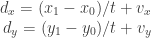
If the bullet takes t frames to reach the bullet, we now get:

\begin{array}{rcl}d_x = (x_1-x_0)/t + v_x \\ d_y = (y_1-y_0)/t + v_y \end{array}

As we said that the bullet’s velocity is V, we get

d_x^2 + d_y^2 = V^2

Which expands out to:

\begin{array}{rcl} \left(\frac{1}{t}\right)^2 \left[ (x_1 - x_0)^2 + (y_1 - y_0)^2 \right] && \\ + \frac{1}{t} \left[ v_x (x_1 - x_0) + v_y ( y_1 - y_0) \right] &&\\ + v_x^2 + v_y^2 - V^2 &=& 0 \end{array}

(I had to split that over a few lines so it would fit in the post column, sorry!)

Which is a quadratic equation! So set:

\begin{array}{rcl} a &=& (x_1-x_0)^2 + (y_1-y_0)^2 \\ b &=&  2[ v_x(x_1-x_0) + v_y(y_1-y_0) ] \\ c &=&  v_x^2 + v_y^2 - V^2 \end{array}

Then, using the quadratic formula:

\frac{1}{t} = \frac{-b + \sqrt{ b^2 - 4ac}}{2a}

You can now put that back into the equations for d_x and d_y, and you’re done!

Here’s the result, written in BlitzMax:

diffx:double=x2-x1
diffy:double=y2-y1
v:Double=3                'desired speed of bullet

a:Double=diffx*diffx+diffy*diffy
b:Double=2*(vx*diffx+vy*diffy)
c:Double=vx*vx+vy*vy-v*v

tInv#=(-b+Sqr(b*b-4*a*c))/(2*a)   ' solve 1/t
dx=diffx*tInv+vx
dy=diffy*tInv+vy

That’s it!